Help & Advice Articles, Videos and How-to-Guides
Filter Articles

How to Install a Kair Heat Recovery Unit
Many houses have mould issues and are looking for simple cost-effective and permanent solutions. The majority of mould and damp problems are caused by condensation due to excess moisture in the air.
Condensation causes mould to grow. The best way to deal with condensation is through ventilation. Ventilation also helps maintain a healthy and comfortable home by removing other indoor pollutants in the air like carbon monoxide and radon gas.
An energy efficient heat recovery unit (also known as a Heat Recovery Ventilator), such as the Kair™ Unit is the ideal solution. These units are designed to alleviate condensation in a single room with major issues and remove indoor air pollutants. This reduces the risk of mould and the risk to health from the build-up of pollutants. These units are designed to tackle condensation in kitchens, bathrooms, bedrooms as well as other rooms throughout the home.
What is a heat recovery system and how does it work?
Heat recovery room ventilators work by continuously changing the air in a room, replacing stale moisture-laden unhealthy air with filtered, fresh, warmed air from outside your home. Heat Recovery Ventilators also help to remove indoor air pollutants such as carbon monoxide and radon gas.
The Kair™ unit also features a heat exchange plate that effectively absorbs heat from the outgoing air and uses it to warm the incoming air. This makes it energy efficient.
Most heat recovery vents will have a boost mode that kicks in when humidity levels reach a certain point. You can set when this boost mode is triggered, allowing you to prevent condensation. Once the relative humidity levels are reduced, the unit returns to a low-energy standard mode.
Kair™ heat recovery unit
Kair™ Heat Recovery Unit work on a continuous air exchange, replacing stale moist air with fresh, filtered and warmed air from outside. They can effectively control the relative humidity levels with a separate sensor to prevent condensation even in problem rooms.
They can be installed in any room in your home including bedrooms, thanks to a light sensor that can prevent it going into boost mode at night which may wake any occupants.
The Kair™ units also deliver the following benefits:
Installing a Kair heat recovery unit
The Kair™ Heat recovery Ventilator is installed through an external wall, which can be installed mainly from inside a building. These units are designed for easy installation with a 152mm core drilled hole.
In this section we will take you through the process of installing a heat recovery unit. Full installation instructions are provided with the unit, but it is beneficial to know what is involved. The installation can be carried out by a confident DIYer, but units should be connected to the electrical supply by a qualified electrician.

Where to install your ventilation unit?
You need to decide on the best place to locate the ventilator. You should survey the property thoroughly, considering rooms with high humidity such as bathrooms and kitchens. The most obvious and most effective areas to install the vent is in rooms that are suffering from the effects of condensation or mould.
Once you have chosen a room, make sure it has an outside wall and that it is free from any obstructions both internally and externally. Obstructions can include water and soil pipes as well as gas flues.
When you are happy that there are no obstructions, you need to mark the position for the core drill hole, fixing holes and power cable entry position (which should be at the top left of centre) on the inside wall. You can do this using the wall plate as a template. You want the unit to be as close to the ceiling as possible to maximise air circulation.
Drilling the Hole
You need a six-inch (152mm) core drill bit. Angle the hole downwards very slightly to the outside - a maximum of 1.5° or 8mm. This will stop any ingress of water from outside.
You now need to measure the length of the hole from the outside brick face to the inner plasterwork. This will allow you to cut the outer tube to the correct length. The units are suitable for wall thickness from 229mm up to 356mm. However, if the wall is thicker than this, you can purchase an extension duct for walls up to 1 metre thickness.
You need the length of the tube to be 4mm greater than the length of your hole, but no less than 254mm. Carefully mark the outer tube all the way around and then cut with a hacksaw. Remove steps and swarf with a file or some good quality sandpaper.

Installing the Unit
You can now place the tube in the hole. Double check that it slopes downwards towards the outside wall.
Fitting the Finisher Ring
You now need to install the split finisher. It is best done from the outside but can be done internally as described below.
Outside Installation of the Finisher
Place the split finisher around the hole in the outside brickwork with the split at the bottom. You should use adhesive to secure it to the wall.
Internal Installation of the Finisher
The split finisher is designed to pass through the large tube so can be installed from the inside. Start by making sure that the external brickwork is dust-free.
- The large tube should be placed in the hole and extend beyond the external wall by 50mm. Apply the adhesive to the rear face of the split ring without compressing it.
- Now hold the finisher in your right hand with your palm facing up and the adhesive side facing you. The split should be at the top. Using your left hand, pull back the righthand end of the split along your right arm. You can now push the finisher through the tube and allow it to expand.
- With your right hand, place the inner flange on the outside of the large tube. Move your fingers in an anticlockwise direction until the finisher is pushed fully onto the tube.
- You can now pull the tube and finisher back towards the room, ensuring that the split remains at the bottom. Carefully pull the finisher into the gap between the tube and brickwork. Press the adhesive gently against the wall, compressing the adhesive slightly.
- Next, pull the tube into the room leaving the finisher in place. Make sure that the finisher does not fall. You can now expand the finisher outwards and increase its internal diameter as much as possible. This will assist the re-entry of the tube. Compress the adhesive fully against the wall to hold it in position.
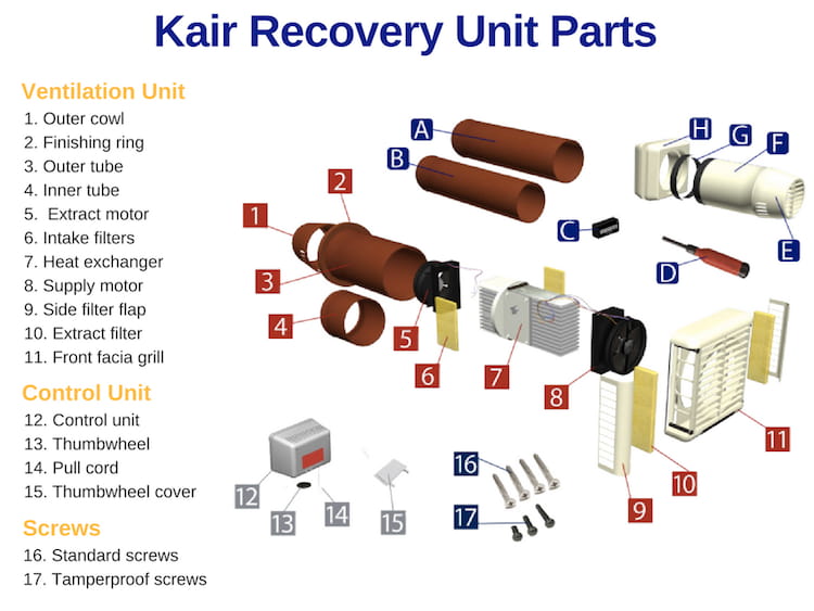
- We now move onto the prepared length of tube. Start by fitting the outside cowl to the length of tube using a PVC adhesive. Apply the adhesive in an even layer around the inside diameter of the tube at the non-cut end. You can now place the outside louvre vent on the end of the tube. You should allow the glue to set before handling it again. Wipe off any excess adhesive on the outside of the cowl.
- To achieve the correct operation of the ventilator, you need the smaller diameter tube (the one that connects the extraction fan housing to the outside cowl, separating the two air streams) to be the correct length. To do this, you need to cut off the exact same length from the inner tube as what has been cut off the outer tube. Try to cut it as evenly as possible with minimum offset. File or finish your cut end to remove any offset and swarf.
- On the heat exchanger you should see a round plastic baffle - this secures the air intake filters. The extraction fan adjacent to these filters goes to the outside wall.
Use the PVC weld adhesive to stick the small tube you have cut to length onto the end flange of the extraction fan and allow the adhesive to set. Always protect the front cover from dirt and scratches.
Fitting the Wall Plate
Here’s how to fit the wall plate to the wall:
- Make sure the wall plate fits flush against the wall and is central in the drilled hole. The wall plate is marked ‘top’ on the front face.
Tip: You can use the remnant piece of large diameter tube as a template to ensure it is central. - Mark out and drill the screw holes. You should also chisel out a groove for the wiring. This needs to lead from the cable entry hole (top left) upwards to the ceiling (or in the direction you have determined for the transformer or remote control). You can now fit the screw plugs into the screw holes.
- Fit the wall plate onto the open end of the large tube with the outside cowl. Measure the distance from the back edge of the wall plate to the other end of the tube. The tube should not extend beyond the outside wall finisher. Use the PVC adhesive to stick the wall plate to the outside tube.
- Make sure that the outside cowl is the right way up (louvres pointing downwards to avoid rain ingress and the louvres are level to the wall plate). Push the outside cowl / tube / wall plate assembly into the hole in the wall. Make sure that top is correctly positioned and pull the cable through the cable hole. Check again that there is a small downwards slope in the tube.
- Screw the wall plate to the wall ensuring that it is level with the ceiling.
It is important to do this now in order to accommodate the angle of the tube in the back of the wall plate before the glue sets.
Fitting the Transformer / Humidity Sensor Unit
The Humidity sensor unit monitors the humidity in the room. It acts as an isolating transformer, automatically switching the ventilator from continuous trickle speed to boost if the humidity exceeds the set point. You can set the humidity level by turning the thumbwheel. This can then be removed to prevent tampering.
Positioning the Humidity Sensor
The Humidity sensor unit can either be mounted on the wall or ceiling. Ideally it should be located on the same wall or one directly adjacent to the stream of the damp air being drawn into the unit.
It should be located at least 150mm from a corner to allow for the correct airflow over the humidity sensor. Avoid locating the humidity sensor unit directly in the stream of the fresh air coming in from the fan unit. This will prevent any false sensing.
Electrics & Wiring
You will need to get a qualified electrician to do the electrics, following the detailed instructions provided by the manufacturer. The positioning of the transformer and humidity sensor unit are particularly key.
You should get them to test the boost mode by putting a steaming kettle underneath and making sure it kicks in.
What happens next? Timeline after the unit is switched on
So, now you have installed your unit and it is fully operational, what can you expect to happen? The following is a rough timeline:
Week One
You might need to make some adjustments during the first few days. Check that the unit is whisper quiet in continuous trickle mode and that the boost mode kicks in when you want it to.
Month One
You should notice a considerable improvement in air quality and a reduction in condensation. You are in a position to redecorate – see following section.
Month Three
Your room should now be free from condensation and any mould issues should be resolved.
Clean the filters - You should clean the outgoing air filters for the first time. Repeat this process every two to three months.
Year One
After a year, you will appreciate cleaner air.
Annual Servicing is recommended where the two larger filters are cleaned.
How to remove existing mould - Redecorating and Making Good
If you suffered from condensation and black mould prior to the installation of the unit, you will want to make good and redecorate any areas that are severely affected. With the Kair™ Heat Recovery System having done its job and the condensation now under control, you can now redecorate with confidence.
You can remove existing black mould with a mould wash. You can then paint over the area with an Anti Mould Paint. This paint can simply be brushed straight from the bucket like a standard emulsion paint. It dries to a matt finish or if you have a preferred emulsion paint you can add our Anti Mould Paint Additive to it to make it mould resistant.
Permagard – Ventilation Experts
At Permagard, we have been helping people solve problems with condensation for decades. If you have any questions in relation to condensation control or PIV systems, then call our technical advisors today on 0117 982 3282 or email us at [email protected].
Further Reading
Read our guide to Ventilating your Home for more information on dealing with condensation. You can also see an overview of damp issues to help understand the issues and solutions. Browse our full range of Ventilation and Condensation Control products.


